JPEN
From an era of "burning" waste to one of "turning it into resources."
HFP adopts a non-incineration gasification technology. No oxidant for combustion (air or oxygen) is supplied; waste is carbonized under low-oxygen conditions. The resulting char reacts with superheated steam (C + H2O → CO + H2) to produce syngas.
The facility is not configured to discharge combustion flue gas from waste through a stack. Classification under Philippine law is a matter for the competent authorities to determine. In its letter dated 28 July 2026, the Planning and Development Department of the Subic Bay Metropolitan Authority (SBMA) refers to the facility as a “Non-Incineration Waste Management Facility.”
No oxidant for combustion is supplied; the feedstock is carbonized under low-oxygen conditions. What is lost is heat (45–55% of input), not elements. The carbon carries forward as syngas.
The process connects directly at the gas stage. It does not produce oil only to break it down again, so the losses that route incurs are avoided.
Carbonization and superheated steam carry the process through to syngas in one line — a differentiated approach to the tar problem that some large-scale gasification projects have encountered.
Emissions are measured continuously and the results disclosed. Acceptance criteria and pre-treatment reduce chlorine load, and the design suppresses dioxin formation through a reducing atmosphere and rapid quenching. Odor is managed by enclosing receiving and pre-treatment indoors under negative pressure.
Four stages convert waste into syngas.
Sorting, washing, drying, and shredding prepare a processable feedstock.
Carbonized under low-oxygen conditions, with no oxidant for combustion supplied.
Char reacts with superheated steam (C + H2O → CO + H2) to form syngas.
The syngas is cleaned. Metals and glass are recovered separately; final residue is mainly ash.
From the cleaned syngas, we produce either methanol or methane — one or the other. The same facility selects between them by switching catalysts; it is not designed to co-produce both. The choice will be made at the FEED (front-end engineering design) stage based on market demand, offtake terms (the buyer's commitment to purchase), feedstock characteristics and plant design conditions.
Conversion to sustainable aviation fuel (SAF) starting from methanol is a subject for future study downstream. It presupposes certification under international standards and falls outside the scope of the current business plan.
* We do not generate or sell electricity. The facility purchases power from the local grid.
* Production volumes, yields and prices will be disclosed once the mass balance is finalised. No figures are confirmed at this time.
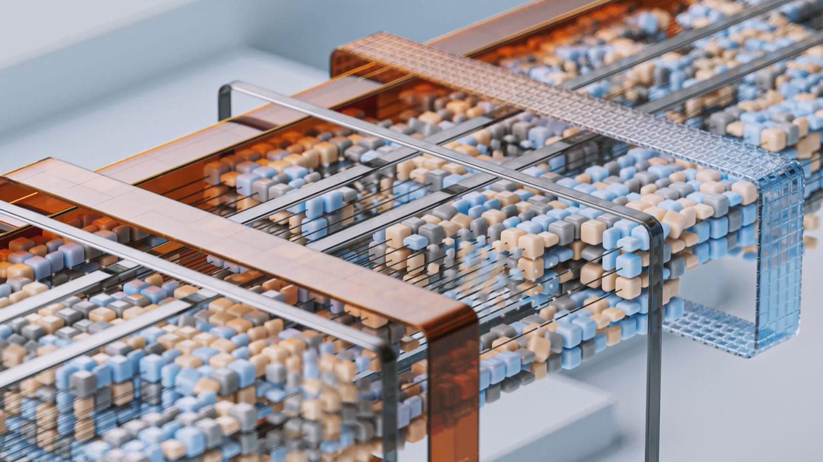
A three-layer digital platform that manages the facility through IoT — equipment connected to the internet for remote monitoring.
Layer 1: Real-time monitoring
Throughput, operating status, and emission parameters are continuously monitored via IoT.
Layer 2: AI predictive maintenance
AI/ML-based failure prediction and operating-parameter optimization raise uptime.
Layer 3: MRV (measurement, reporting and verification) automation
Automates the measurement, reporting, and verification of emissions data, and generates reports for LGUs (local government units) and government.
Operating data accumulates in a form that can be disclosed. That is what backs the next step.